
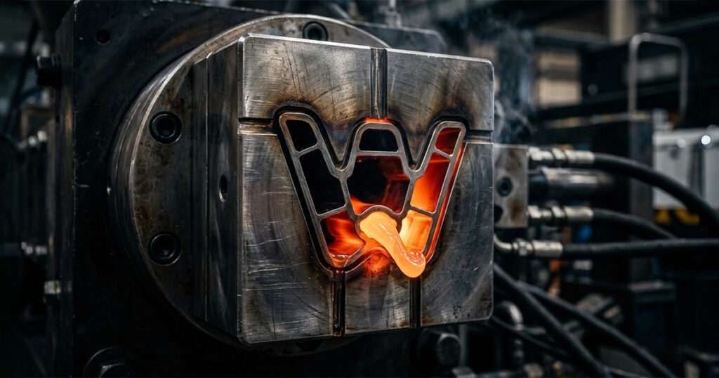
The Foundation of Precision: Why Design Dictates Tool Life
Industrial-grade mold making requires substantial capital investment. To ensure a maximum return on investment (ROI), a mold must be engineered to withstand millions of high-pressure cycles without exhibiting structural fatigue, parting line mismatch, or dimension drift.
Proper tool design begins with structural calculations that anticipate the massive clamping forces (often ranging from 50 to over 1,000 tons) exerted by the injection press. Our engineering team selects premium certified tool steels based on the targeted production volume:
Class 101 Tooling (High Volume): Utilizing hardened steels such as H13 or 420 stainless steel, engineered for over one million cycles.
Class 102/103 Tooling (Medium Volume): Utilizing pre-hardened steels like P20, ideal for complex technical parts with moderate production runs.
Without an engineered design that accounts for these mechanical stresses, even the most expensive steel will succumb to micro-fractures, core deflection, or premature wear, proving that elite mold making is impossible without flawless upfront design.
Strategic Gate, Runner, and Venting Layouts
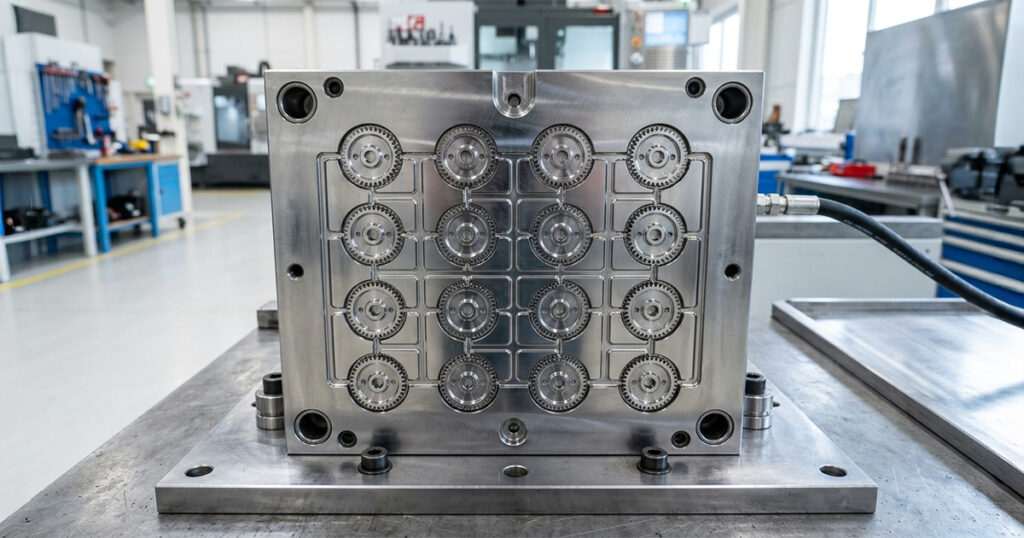
A mold is essentially a specialized heat exchanger and a pressure vessel combined. How the molten polymer enters, travels through, and cools within the cavity depends entirely on internal architectural design:
A. Gating Architecture
The gate is the threshold where molten plastic enters the cavity. Its location, size, and geometry affect how the polymer molecules orient themselves. Poor gate placement leads to high internal residual stresses, visible knit lines (where two flow fronts meet), and structural weak points. Through advanced simulation, our plant ensures gates are placed away from high-impact or mechanical load zones of the industrial part.
B. Runner System Efficiency
Whether utilizing cold runner or hot runner systems, the design must guarantee balanced filling across all cavities. In multi-cavity mold making, unbalanced runners cause some cavities to pack early while others under-fill (short shots), leading to unacceptable dimensional variances within the same production batch.
C. Micro-Venting Optimization
As plastic rushes into the mold, the air inside must escape instantly. Inadequate venting traps gases, leading to localized compression heat that burns the plastic resin or creates voids. Our designs feature micrometric vents strategically placed at the last areas of the cavity to fill, allowing clean air evacuation without creating flash.
Conformal Cooling: The Key to Shaving Seconds Off Cycle Times
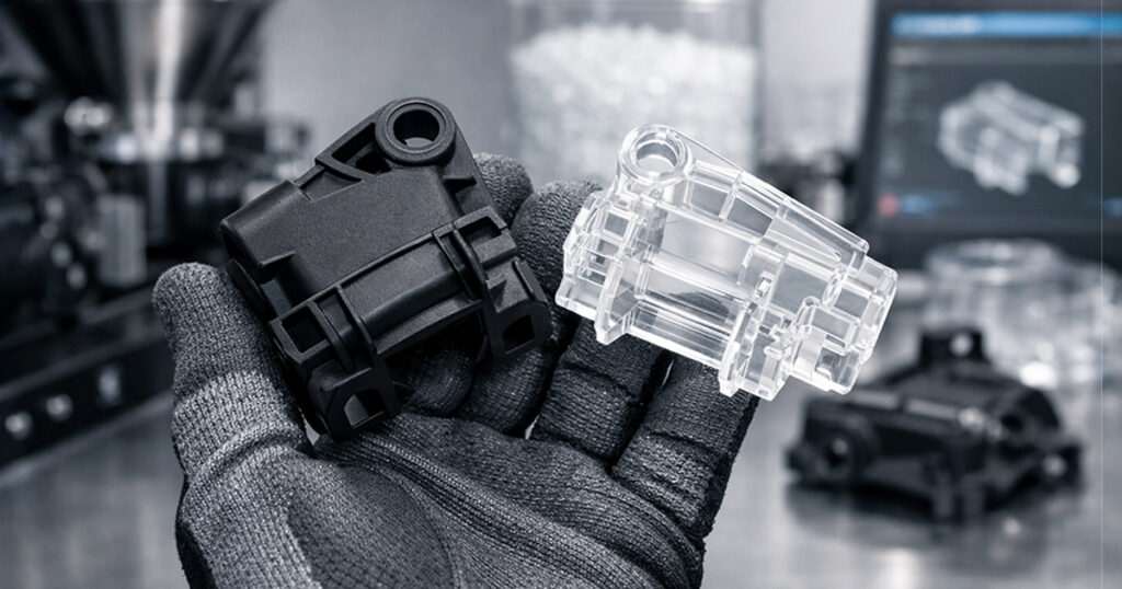
In high-volume industrial manufacturing, time is measured in fractions of a cent. Roughly 70% to 80% of the entire injection molding cycle is dedicated exclusively to cooling the plastic part until it is rigid enough to be ejected.
Traditional mold making relies on straight-drilled cooling lines, which often leave hot spots in deep corners or thick sections of the part, causing uneven shrinkage and warping. At Sumiparts, our engineering plant utilizes advanced computational design to create conformal cooling channels. These curved, complex paths mirror the exact topology of the component’s geometry. By maintaining a uniform thermal delta across the cavity walls, we drastically accelerate heat dissipation, reduce cycle times by up to 20% to 40%, and ensure the part remains perfectly flat and true to print.
In-House Manufacturing: Bridging Design and Execution | Mold Making
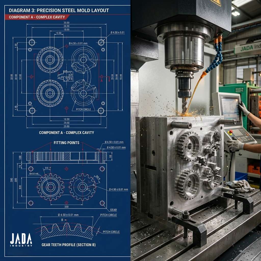
The primary vulnerability in sourcing industrial components is the disconnect between the design firm and the machine shop. The Sumiparts plant eliminates this risk by operating as a fully integrated turnkey facility.
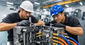
Our tool designers work alongside our CNC programming and EDM (Electrical Discharge Machining) technicians. When a mold design is finalized, the digital CAD data transfers directly to our high-speed machining centers and wire EDM stations. This seamless data loop ensures that the physical mold reflects the micrometric tolerances calculated during the simulation phase. Furthermore, having our mold making division in the same plant as our injection molding presses allows for immediate, real-world tool tuning and rapid prototyping verification.
Protect Your Assets with Engineered Tooling
A cheap mold design is the most expensive mistake an industrial operation can make. It results in slow cycle times, high reject rates, frequent maintenance shutdowns, and premature tool failure. Partnering with the Sumiparts manufacturing plant ensures that your mold making projects are backed by rigorous mechanical engineering, thermodynamic optimization, and advanced metallurgy. Let our team design and build the robust tooling required to power your continuous high-volume production.
Deep Technical Block: Calculating Volumetric Shrinkage and Draft Angles | Mold Making
To fulfill the analytical expectations of Production Directors and Quality Engineers, it is necessary to highlight the mathematical precision behind draft angles and shrinkage allowances in mold making. Every polymer contracts as it transitions from a liquid to a solid state. If a mold cavity is cut to the exact final dimensions of the blueprint, the resulting plastic part will always be undersized.
Our tool designers apply specific scaling factors to the core and cavity inserts, factoring in the specific shrink rate of the polymer (e.g., 0.005 in/in for Polycarbonate vs. up to 0.020 in/in for unreinforced Nylon).
Equally critical is the integration of draft angles on all vertical walls parallel to the draw direction of the press. Without a calculated taper (typically 1° to 2° per side, increasing for textured surfaces), the contracting plastic will lock onto the steel core. During the ejection phase, the mechanical force required to push the part off the steel will cause scuff marks, stress whitening, or structural tearing.
By calculating the exact friction coefficients between the polymer and the treated tool steel, our mold making division ensures effortless ejection profiles, preserving the cosmetic finish and dimensional accuracy of the component across long-run production campaigns.
Managing Core Deflection and Parting Line Realignment | Mold Making
In deep-draw industrial parts, such as cylindrical housings or long structural brackets, the mold core experiences immense hydrostatic pressure as the molten plastic is injected at high velocities. This pressure can cause a phenomenon known as core deflection, where the steel core shifts slightly to one side, resulting in uneven wall thicknesses on the final plastic component.
To mitigate this mechanical risk during the mold making engineering phase, Sumiparts designs interlocking core supports, taper locks, and hydraulic slide cores that mechanically lock the tooling components into absolute position before the resin enters.
Additionally, we precision-grind the parting lines—the boundary where the two halves of the mold meet—to tolerances under 0.01 mm. This micro-precision grid eliminates the formation of flash (excess plastic bleed), reducing the need for manual post-processing and ensuring that the structural integrity of your high-performance parts remains completely uncompromised.
Learn More...
Want to learn more about our Making Mold Services?
SUMIPARTS is dedicated to serving you. We strive to bring the best solutions directly to you, whenever you need them. Reach out to us via PBX at + 57 601 748 22 13, call us at +57 313 699 13 56, or email us at grupoempresarial@sumiparts.com. Our team is eager to provide the support you deserve.



 English